
-
Dielectrophoretic pump
Created by Zoltan Losonc (feprinciples@on.mailshell.com) on 4 July 2003. Last updated on 14 July 2003. Linguistic proofreading done by Steven Dufresne.
Zoltan Lozong explains along this amazing study how one could extract exergy from diephoretic process.
Rectangular flat capacitor
In the tutorial about electrostatic forces in dielectrics we introduced the dielectrophoretic force that creates a pressure-difference at the edge of a flat capacitor when merged into a liquid dielectric, and pushes up a liquid column between the plates (fig. 1a).
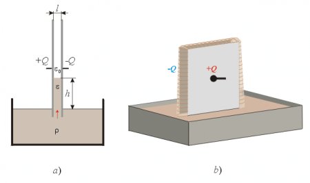
Fig. 1.
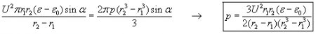
We have derived the formula for the force that pushes the liquid column upwards, and it is:
The pressure increase at the bottom edge of the capacitor can be calculated from this as:
The pressure p in our discussion actually means a pressure-difference Δ p and not an absolute pressure.
Dilemma of leakage
Two questions may arise naturally in connection with this setup. The first question is whether the liquid would pour out from the elevated liquid column at the front- and back edges when they are left open. The other question is whether a jet of liquid would be ejected upwards into the air (like a fountain) when the height of the capacitor is lower than the calculated height of the liquid column between the plates. If this would be possible then a very efficient pump and fountain could be constructed since the pumping effect does not require any current flow but only static high voltage. By covering the plates with a very good solid insulator layer, and using a liquid dielectric of high permittivity and high resistance, the current could be minimized and the power consumption reduced to an insignificant value compared to the power generated by the pumping effect.
The answer to one of these questions answers both questions because the same principle determines both these phenomena. If the law of energy conservation has to remain valid, then the liquid may not flow out either at the open side edges or at the top of the capacitor since then a closed loop movement of the liquid would be established - producing energy - while theoretically (using very high resistance dielectrics) requiring no electric current and no input power to maintain the pumping effect. This explanation of the classical science seems to be supported by the fact that the electric field is the same at all four edges of the capacitor. Thus the same force is supposed to push the liquid dielectric into the capacitor at all sides when it reaches into the inhomogeneous E-field region of the edges where the pumping forces appear. According to this interpretation the liquid would flow into the inhomogeneous E-field region outside the plates, but it would stop there, held back by the dielectrophoretic forces, and form an arced convex liquid surface (fig. 1b). In practice this might not be fully realized, since at the edges that are not fully surrounded by the dielectric (above the liquid surface) some little force component will be missing that would otherwise be generated by the weak E-field farther away from the edges if the whole capacitor were surrounded with the liquid. Thus the dielectrophoretic pressure at the bottom edge (where there is a deep space below, filled with dielectric) will be slightly stronger than that at the edges above the liquid surface, and a weak leakage might appear. However the pressure-difference will be minimal and cannot provide an efficient pumping effect. So as a first step approximation we can assume that the law of energy conservation is satisfied in this case, and that no significant pumping effect can be achieved that would pump the liquid through the capacitor, since the inward sucking forces are nearly the same at all four edges, and the retarding force at the outlet will cancel the upward pumping force at the bottom input.
Diminished retarding pressure-difference at a hole outlet
However we may try to go around this difficulty by not expecting the liquid to flow out at the edges, where the retarding forces are strong (sealing the edges), but through a hole drilled into the middle of the grounded plate, as shown in fig. 2.
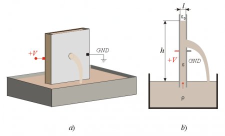
Fig. 2.
Now the question is how much retarding pressure-difference will be generated at the hole outlet by the dielectrophoretic forces, and whether this retarding force will be less than the pumping force at the bottom edge. This is a difficult question to answer without measurements since the shape of the E-field at the hole is fairly complex as shown in fig.3a. But we have good reason to suspect that the forces will be less intense here because the E-field is less intense outside the hole (the plate is grounded) compared to the E-field intensity at the edges of the capacitor. Naturally the indirect method for calculating the forces is not applicable in this case since that can yield a correct result only if the law of energy conservation is valid. Thus that method would not allow any possibility of leakage from the capacitor.
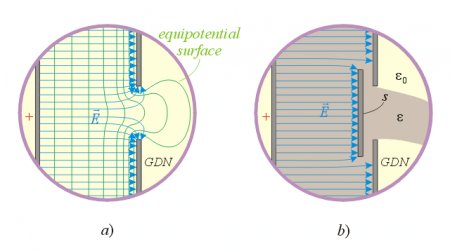
Fig.3.
The fig. 3a. shows a slightly inhomogeneous and arced E-field shape that can still produce significant retarding force. Let’s try to find some arrangement that could minimize the curvature and inhomogeneousness of the E-field at the hole. One such possibility is shown in fig. 3b, when a parallel shielding plate is placed in front of the hole and connected to the ground together with the right electrode of the condenser. The shielding plate s ensures a more uniform E-field distribution, and this arrangement might produce less dielectrophoretic resistive force in the way of the flowing liquid. All this is written in conditional mode, since without numerical analysis or exact measurements we cannot know the magnitude of the forces at the hole.
However our endeavor to theoretically violate the law of energy conservation is not completely hopeless, and we will do the impossible and prove the invalidity of energy conservation for the complete system in some special arrangements, based on (and assuming) the local validity of energy conservation for each single component of the system.
Flat disc capacitor
In order to find the possible components of such a FE system, we should derive the formulas of the dielectrophoretic forces for each element through mathematical analysis, firmly based on the assumed validity of energy conservation for each component. In the case of a rectangular flat capacitor this has been already done (see above), and now let’s see if there is any difference if we use disc-shaped electrodes instead of rectangular plates (fig. 4a).
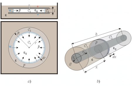
Fig. 4.
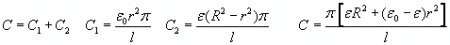
The flat disc capacitor is fully merged into the liquid dielectric but there is a flexible, movable wall w between the electrodes (perpendicular to the plates) that prevents the liquid from entering into the center part of the capacitor which is filled with air. Let us calculate the force that is squeezing this insulating wall towards the center, and also the pressure within the capacitor caused by the dielectrophoretic forces at the edges. The capacitance of the condenser is:
The electric energy in the condenser is:
The electric energy change of the capacitor per wall movement, when the radius of the wall is changed is:
The force upon the wall is:
The pressure of the liquid inside the capacitor is:
This is the same formula as that of the rectangular flat capacitor and both produce the same dielectrophoretic pressure.
Coaxial cylindrical capacitor
Now let’s do the same calculation for the coaxial capacitor shown in fig. 4b.
In this case the force is directed towards the increase of x, thus:
This is an interesting result since the pressure-difference of the coaxial capacitor is not the same as that of the rectangular- or disc shaped flat capacitors using the same dielectric, voltage, and distance between electrodes. This difference can provide a firm ground for the establishment of the asymmetry in pressures and the consequent violation of the energy conservation.
Semi-cylindrical capacitor
Before analyzing this possibility, let us calculate the force and pressure in the case of a semi-cylindrical capacitor (fig. 5).
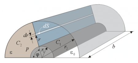
Fig. 5.
The energy stored in the capacitor is:
The torque is calculated as:
 (1)
(1)Supposing that the torque is caused by a homogeneous pressure, it is calculated as:
Equating this expression with the formula (1) we get the pressure:
The total force developed by this pressure upon the capacitor is:
Hemispherical capacitor
The examined capacitor is shown in fig. 6. The capacitance is:

The energy content of the condenser is:

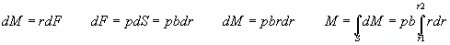
We want to calculate how much pressure would be required to create the derived torque. This is done by assuming a constant pressure over the examined half circle-ring area, and integrating the elementary torques to get the resultant torque M (fig. 6b)
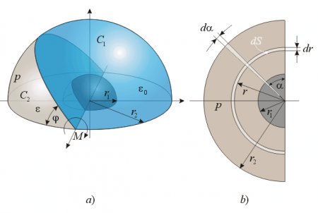
Fig. 6.


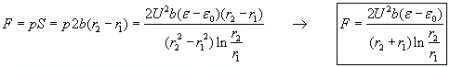
By equating this torque resulting from the pressure-difference with the above formula (2) we get the pressure:
Supposing that this pressure is the same over the whole surface area of the circle-ring between the bottom edges of the hemispherical capacitor, the force upon the condenser is:

These formulas for the hemispherical capacitor have been derived using a torque around an axis, and a doubt may arise about its correctness. Therefore the same formulas have been derived with another method, assuming that the dielectric rises into the capacitor through the whole open bottom surface area simultaneously, and develops a torque around a single point at the center. The calculation can be found in the appendix.
Analyzing the results
The following table summarizes the derived formulas of the pressures and forces at the open edges of the different capacitor types:
pressure
force
Rectangular flat capacitor
Disc-shaped flat capacitor
Cylindrical coaxial capacitor
Semi-cylindrical capacitor
Hemispherical capacitor
Pressure-differences pd = pr and px = pc, thus we have only 3 different pressure-difference for the 3 different electrode shapes. The following diagram compares these pressure-differences for changing r1 (radius of the smaller electrode) with fixed r2 = 5mm and uses the following parameters: l = r2 – r1 ; U=10 kV ; e =56e 0 (the permittivity of glycerin).
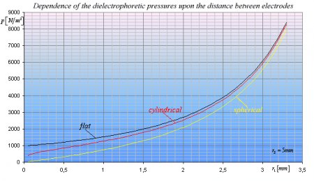
Diagram 1.
The pressure-difference ratios of flat-cylindrical and flat-spherical condensers are:
The curves nicely illustrate that when r1 approaches r2 all 3 pressure-differences will become nearly identical (right side). However when r1 is much smaller than r2, there will be big differences between the pressure-differences. For example when r1 is 10 times smaller then r2 then pf=1.4pc and pf =3.7ps. When r1 is 100 times smaller than r2 then pf =2.35pc and pf =33.67ps.
Complete pump configurations
With a clever arrangement we can exploit these pressure-differences to create an efficient electrostatic pump that violates the law of energy conservation. A flat capacitor’s edge should be merged into the liquid dielectric, since that gives the highest pressure-difference; and a smooth transition should be made to a coaxial cylindrical capacitor, that in turn should end in a semispherical capacitor where the fluid leaves the condenser, since the retarding pressure-difference is the lowest for that shape (fig. 7).
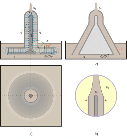
Fig. 7.
At the curved region t where the flat disc capacitor merges into a cylindrical coaxial capacitor, the E-field lines are straight and thus do not retard the flow of the liquid. There will be a dielectrophoretic force towards the center of curvature O that is perpendicular to the movement of the fluid, tending to push it against the wall of the upper electrode, but not retarding the movement of the dielectric. The only retarding pressure-difference appears at the top opening, and that pressure-difference of the semispherical condenser has just been calculated to be less than the pressure-difference of the flat capacitor at the bottom. Thus the resultant pressure-difference that this pump can create is calculated as:


If the output ending would not have the semispherical shape, but is left to be the natural ending of the coaxial capacitor (fig. 7b), then the resultant pumping pressure-difference would be:
The dependence of these pressure-differences from the radius of the inner electrode of the cylindrical part r1 and voltage is shown in diagram 2.
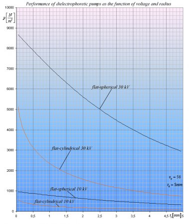
Diagram 2.
The semispherical outlet shows a better performance than the simple cylindrical coaxial capacitor ending. Other possible pump shapes are shown in fig. 7c. and fig. 8, which have basically the same performance as the one shown in fig. 7a. How high can these pumps elevate the liquid column? The formulas for spherical and cylindrical endings are:
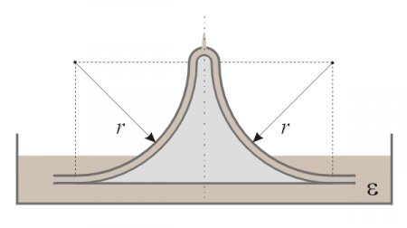
Fig. 8.
Violation of the law of energy conservation
After deriving the formulas, and supposing that there is no major flaw in the derivation, we have arrived to a weird contradiction:
- If the law of energy conservation is valid for the basic shapes of capacitors, then the derived formulas for the dielectrophoretic forces, torques, and pressure-differences must also be valid. If they are valid then the formula for the resultant pressure-difference of the described dielectrophoretic pump (made from a special combination of these elements) should also be valid, and significantly greater than zero. But if the resultant pressure-difference of the pump is greater than zero then the law of energy conservation is violated for the whole pump, since at least theoretically no electric current is required for its operation (but only high static voltage) and thus no input power is consumed. Theoretically this pump can produce mechanical energy without consuming input energy.
- On the other hand, if the pump does not produce a resultant pressure-difference between its input and output (in which case the final formula would be invalid), then the law of energy conservation is violated for the basic capacitor shapes, since the final formula for the resultant pressure-difference of the pump has been derived as the sum of the correlations of each basic shape. In that case we could use the basic capacitors individually to produce excess energy with proper arrangements.
It seems that there is no possibility to satisfy the law of energy conservation simultaneously for the whole pump and also for each basic capacitor shape component. The above conclusions assumed that the liquid dielectric is a very good insulator and it does not allow any current flow. In practice there is always some leakage current that can be minimized by carefully choosing the liquid dielectric and optionally covering the electrodes with a very good solid insulator layer. But even if there still would be significant leakage current, the law of energy conservation would be still violated, since the input power (caused by the unwanted current) is fully transformed into heat and into accumulation of electrostatic charge (and energy) on some bodies. Thus the input power is not consumed for the propulsion of the liquid, but for producing heat, thus the kinetic energy represents an excess energy that still violates the law of energy conservation.
Increasing the amount of excess energy generated by the pump
How much energy can we generate with the pump? Knowing the produced pressure-difference it is easy to calculate the power:
Where p – is the pressure-difference; dV - is the elementary volume; dt – time difference; S – surface area; v – velocity of the liquid.
The pressure-difference p and the surface area through which the liquid flows out are determined by the size and other parameters of the pump. However, the velocity v of the liquid dielectric is not definitely determined. This velocity would be limited only by the length of the accelerating path and the frictional resistance of the fluid path. Since the pressure-difference does not depend on the velocity of the liquid but is constant, the possibility naturally offers itself to artificially create an external additional pressure-difference by connecting an external pump in series with the dielectrophoretic pump, and this way further increase the velocity of the dielectric. The external pressure-difference can be generated by any conventional means and the increased velocity increases the excess energy. To calculate the increase of excess energy let us assume that the velocity of the fluid through a pipe is linearly proportional with the pressure-difference v=Kp. The input power consumed by the external conventional pump is then:
The output power is:
The excess power is:
If there would be no external pump increasing the velocity then the excess energy would be , thus the external pump increases the excess energy by the factor of:
If the external pump provides 9 times higher pressure than the electrostatic pump then the excess energy generated by the electrostatic pump will be 10 times greater than without external pump. The COP of the whole system is:
When the external pressure-difference is much higher than that of the dielectrophoretic pump then the COP approaches unity. Naturally the best is to use dielectrophoretic pumps also as external pumps, thus they would not consume significant energy, and the COP could be maintained at high value.
Questions to be clarified by measurements and numerical analysis
- A future task is to verify the validity of the derived formulas for the basic capacitor shapes, and if there is significant deviation between the predicted and measured pressures, new correct formulas and applications should be created.
- The dielectrophoretic pressure should also be measured for special openings (intended to provide low pressure-difference output) as shown in fig. 3 to clarify their applicability.
- It is an interesting question whether the dielectrophoretic pressure will depend on the shapes of the edges as shown in fig. 9. According to the law of energy conservation all these edge shapes should produce identical pressure-differences, however the different E-field distributions justify practical verification.
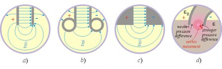
Fig. 9.
- Another important fact to be aware of is that in the case of semi-cylindrical and hemispherical capacitors the dielectrophoretic forces upon the molecules of the dielectric will be stronger at the smaller electrode since the E-field intensity is strongest there. Thus we can expect a higher pressure-difference near the smaller electrode and a lower pressure-difference at the bigger electrode. Such pressure distribution would generate fluid vortexes at the edges, which are not beneficial for the pumping effect (fig. 9d). However if such vortexes do exist and they are sufficiently strong then they can also provide free energy. This effect should also be verified experimentally.
An alternative derivation of the pressure-difference and force for the hemispherical capacitor shape
Using this method we assume that there is a flexible frustum of a cone between the electrodes with vacuum (or air) inside, and that the space below the cone is filled with the liquid dielectric that is squeezing the cone as in fig. 10a.
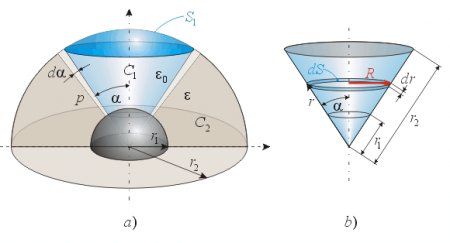
Fig. 10.
The capacitance of a full spherical condenser is:

The capacitance of a sphere segment is proportional to its outer surface area (or in other words, with the space angle viewed from the center of the capacitor), thus the partial capacitances are calculated as follows.
The outer surface area of the conical sphere segment C1 (fig. 10a) is
 . The total surface area of the sphere is
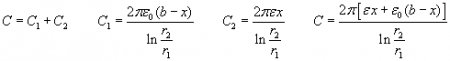
  . The partial capacitance C1 can be calculated when the capacitance of the full spherical capacitor is multiplied with the quotient of these two surface areas:


The electric energy of the capacitor is:
The energy change per angle displacement:
Thus the torque around the center point should be:
Let’s now calculate the torque on the frustum of a cone if the liquid pressure is constant everywhere on that surface area (fig. 10b):


Equating this formula with (3) we get the wanted pressure difference:
This formula is the same as derived above with a different method, thus it is correct.
NOTE: The above figures have been made manually based on rough estimations, thus the E-field shapes are not based on numerical analysis or exact analytical calculations. The real E-field shape might be somewhat different than what is shown in the drawings. These illustrations serve only for the purpose of aiding the understanding of the presentation.
Created by Zoltan Losonc (feprinciples@on.mailshell.com) on 4 July 2003. Last updated on 14 July 2003. Linguistic proofreading done by Steven Dufresne.
