-
The magnet perpetual wheel
-
The magnet perpetual wheel
Creation date: 11th of August. 2012
The perpetual wheel driven by a permanent magnet
The inventor
The concept of this perpetual wheel has been patented in 1823.
That invention is fully described in book "Mechanical Appliances and Novelties of Construction" published in 1927 by Gardner D. Hiscox, Mechanical Engineer, and Norman W. Henley.
The engine described in the video herebelow is of a relatively simple design.
Description of the invention concept
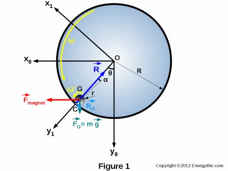
A strong magnet set in the open slot between sides of the wheel attracts an iron ball.
The magnet is supposed to draw the ball to one side of the center to make the wheel permanently unbalanced.
It is important to note that the static potential energy of the magnetic force is converted into pure kinetic energy.
Theoretical study of the perpetual wheel

We assume that the ball rolls and slips on the inner track of the wheel.
The various inventoried losses of this motor are :
- Rolling friction losses ( Rrf ) of the ball on the inner track of the wheel and resulting from local deformation of the raceway under the weight of the ball,
- Power losses due to sliding of the contact surfaces of the ball and raceway (ω' is greater than ω),
- Loss of two ball bearings installed on the axis of the wheel.
Balance of forces
Balance of forces along y1 axis :

Balance of forces along x1 axis :

We have the following relationship between Rrf and R :

Then, it comes:

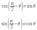
Expressing the following equalities :

It comes then :

In this formula, the following terms are known: F magnet, m, g, α and θ. α is the angle of the rolling friction.
The combined gravity and magnetic forces cause an unbalance of the rolling ball which is not compensated by an equal and opposite reaction force. The ball is forced to rotate and this rotation drives the main wheel by means of rolling friction force.
Due to violation of Newton's third law, there is creation of excess positive energy from potential energy supplied by static magnetic and gravitic fields.
Static potential energy is thus converted into kinetic energy by that perpetual wheel.
Calculation of drive torque
The drive torque is equal to Tdrive = Fresulting x r , soit:

Calculation of inlet power
Excepting parasitic movements linked to instantaneous instabilities of operation and taking the assumption of a constant angle theta, one can verify that the magnetic and gravity forces provide no power to mechanism. These two forces are involved only in maintaining an unstable state. Then:

Calculation of drive power
The sliding coefficient rslip of the ball on the inner race of the wheel is expressed by the following formula:
 , then :
Let's calculate the drive power : Pdrive = Tdrive . ω'

with

Let's calculate the outlet power : Poutlet = Fresulting . R . ω

It has to be noted that:

and :

Calculation of COP (coefficient of performance)
Pnet outlet = Poutlet- Pwheel friction losses
Pwheel friction losses = 1% Poutlet and
Pnet outlet = 0,99 Poutlet

Calculation of COE (coefficient of energy)

Numerical application
r = 0,015 m - R = 0,15 m - g = 9,81 m/s² - θ = 30° - tan α = 0,001 - r slip = 10% - ω = 60 rpm = 6,2832 rd/s - B = 0,4 T - μ0 = 4 π 10-7 - μr = 1,0000004 - S = 0,01 x 0,01 = 10-4 m²
Fmagnet = 6,366 N
m = 0,014 kg
Fresulting = 5,442 N
Tdrive = 0,041 mN
Pdrive = 5,700 W
Poutlet = 5,130 W
P rolling losses = 0,570 W
P net outlet = 5,078 W
P wheel friction losses = 0,052 W
COP = ∞
COE = ∞
Improved mechanism
An improved design of the mechanism would consist to machine teethed surfaces on the inner track of the wheel and the outer surface of the central part of a cylinder (ball replaced by a cylinder). Each end of the cylinder has a rolling cylindrical surface of same diameter as the gear pitch diameter on central part.
Thus, the sliding of the two contact surfaces is cancelled and the operation of the wheel is more stable.

