-
Isolated self-propelled systems by electrostatic forces
-
Isolated self-propelled systems by electrostatic forces
Cliquer pour charger le document en Français Systèmes isolés auto-propulsés par des forces électrostatiques
Introduction
The electrostatic in general education, is often studied in a summary manner, as a preamble to much larger and detailed courses that relate to electrodynamics.
In fact, the electrostatic is an extremely complex science that uses the laws of classical physics (macroscopic domain), of quantum mechanics (electron, hole, orbital ...) and relativistic physics since any vector field has the feature warping the space-time continuum in which it circulates.
So far, electrostatics was considered as a science related to polarized conductors and which are in equilibrium due to the symmetry of the action-reaction forces.
We will endeavor to demonstrate that the balance between polarized hardware subsystems, constituting an isolated system, is actually a special case.
This article offers some embodiments, non-limiting, which can break this symmetry:
- a suitable geometry of polarized surfaces,
- the use of dielectric correctly arranged,
- the introduction of induced charges,
- a judicious distribution of the potential into (2n +1) polarized frames.
All proposals are made in the vacuum, require a near-perfect machining of the frames and the use of flawless dielectric.
Symbols and writing convention
To differentiate the text and symbols, they will be shown in brackets when the clarity of the presentation makes it necessary. Observers are selected with a clock that measures the time ( t ) of a vector space, an affine Euclidean space and of a reference frame. The reference frame related to spacetime quantinuum will be considered as Galilean and will be called ( R0 ). We use the following symbols:
- ε : absolute permittivity coefficient,
- ε0: relative permittivity coefficient of the vacuum,
- εr: relative permittivity coefficient of a dielectric,
- E: electric vectorial field (or electrostatic),
- V: potential,
- ΔV: potential difference,
- q: electric charge,
- S: surface,
- V: volume,
- ρ: volume charge density,
- σ: surface charge density,
- C: capacitance of a capacitor,
- W, T: energy, work,
- P: pressure per unit volume,
 : variation between the initial α and final β states,
 : normal unit vector elevated on the surface element,
 : unit vectors of the reference frame (O, x, y),
 : force.
Any element (frame, dielectric, continuum ...) will be attached to a reference frame (R).
A force that acts between two elements will be represented by the symbol
 , which means that is exerted between the referential frames ( Ra et Rb ), and it is directed from the first ( Ra ) to the second ( Rb ).
Thus,
 .
.In symbol
, we associate the indicesthat correspond to the unit vectors of axes ( Ox ) and ( Oy ) along the directionfrom the reference system attached to the Galilean space-time continuum ( R0 ), example  is where the forceis supported by the unit vector ( i) of axis ( Ox ) and directed from ( Ra ) towards ( Rb ).
A force that acts on two material reference frames
will be called a bond strength.Force sustained by a conductor
It is assumed that all the laws of electrostatics are known to the reader. We limit the reminders to the only force experienced by a conductor.
The energy of a charge distribution is equal to
 , where electric charges ( qi ) are raised to the potentia ( Vi ), and that of a capacitor is equal to
  , where C measures the capacity.
The pressure ( P ), in the thermodynamic sense of the term, is equal to the energy per unit volume or with (e) gap between the plates surface (S):
 with
with  (plane capacitor) , v = e S and q = σ S, it comes:
With a plane capacitor, one has the following equation:
 either

Then we have:
 and, taking the unit vector to elevated normalon the surface, we have:
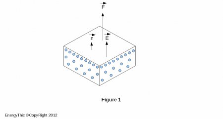
It is extremely important to note that this force (called expansion force) is of the type action force, either
 because it occurs between a frame (Ra) and the space-time continuum (R0) that contains
 .
.It is also important to note that the vector
is still supported by the normalto the surface of the polarized element. If a dielectric of relative permittivity coefficient ( εr ) touches the conductor, the force is multiplied by ( εr ) if the potential ( V ) is kept constant.Force sustained by dielectrics
Neglecting the depolarizing field that exists within the dielectric, we can say schematically that a dielectric:
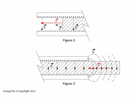
- which sustains an external vectorial field, collinear with the surface between the dielectric ( εr.ε0 ) and the vacuum ( ε0 ), which must also be considered as a dielectric, experiences a surface force (see Figure 2) equal to:
oriented along the normal
to the element ( dS ), and directed towards the vacuum, ie towards the lower coefficient of permittivity. - which sustains a gradient of electric field, generates therein a volume force (see Figure 3) equal to:
that can be reduced to a surface force (provided that
 ) either:
that is brought about ( dS ) where the electric field is constant.
Which interest presents the electrostatics ?
The electrostatic presents a double interest, because of the expansive forces that are of action force type (as resulting from the interaction of polarized scalar magnitudes on a vectorial field) and because it allows man to shape these forces to his liking, as a module that direction.
In mechanics, the forces acting between two material systems ( Ra ) and ( Rb ) are binding forces which act between two centers of gravity (see Figure 4).
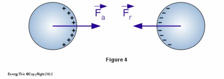
The forces
and  are borne by a straight line, have the same module and an opposite direction, therefore:
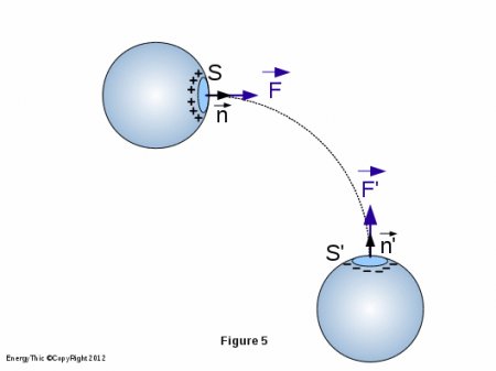
In electrostatic, by against, the forces of expansion:
- result from an interaction between the electric charges ( σ ) carried by the surface element ( dS ) (see Figure 5) and the electric vectorial field , either
 , it is therefore a force of action,
 - are still carried by the normal to the surface element. Since the field line is not straight but curved, it appears that the resultant force is different from zero, as shown schematically in Figure 5.
Finally, it should be noted, contrary to widespread belief that the expansion forces can reach astronomical figures. Here are a few examples. They are not limiting. They have as main interest to show different possible models to obtain a broken symmetry, ie to obtain an resulting expansion force different from zero.
Expansion force resulting from asymmetric geometry of frames
Description
Consider a parallelepiped (item 1) in which we set:
- on the lateral sides, 2 metal frames (item 2) connected to the negative pole of a generator,
- on the underside, a central metal frame (item 3) connected to the positive pole of the same generator.
One gives the upper end of the frame a positive profile called constant field, ie the vectorial field
 is identical at any point of the frame, whether in its flat or curved portion.
This profile is obtained using the theory of conformal transformations.
The parametric equation of this profile is:

The positive frame (item 3) is a thick plate of thickness ( 2 e ), the spacing between the central frame (positive) and each side frame (negative) being equal to ( e ), with
 , since:
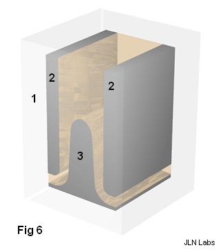
x -∞ 0 -∞ y 0 -π/2 π Naturally, we must not give the same profile in the upper part and lower part of the central frame, otherwise the resulting force would be zero. It is appropriate to adopt a geometry that creates a different force at both ends. There are several solutions to this. Consider that which consists in giving (see Figure 6):
- to the lower part of the side frames a quarter-circle shape (convex portion),
- to the lower part of each side of the central plate a quarter-circle shape (concave portion), while maintaining the spacing ( e ).
The available volume between the plates is filled with a solid dielectric, homogeneous and having a high ( εr ). If the parallelepiped is made with the same dielectric, we obtain a dielectric block in which the frames form inclusions.
Charge the capacitor and then isolate the capacitor plates.
To facilitate the identification of strengths, we will take a referential ( O, x, y ) with unit vectors ( i ) and ( j ) and we will split the system into three isolated areas including (see Figure 7) :
- (A) the upper curved part of the central frame,
- (B) the flat part of the central frame,
- (C) the lower curved portion of the central frame.
Identification of expansion forces
Area A
Consider ( see Figure 8 ) a surface element ( S0 ) of the central frame, small enough to assimilate it to a portion of the plan.
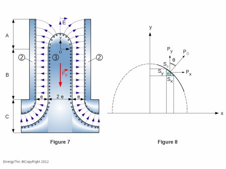
Project ( S0 ) onto the axis ( Ox ), either ( Sx = S0 cos θ ).
Consider the electrostatic pressure P0 which is applied to the surface S0. Express the product P0.Sx.
We can write: P0.Sx = P0.(S0 cos θ) = (P0.cos θ).S0= Py.S0
Thus: P0.Sx = Py.S0
In the same manner: P0.Sy = P0.(S0 sin θ) = (P0.sin θ).S0= Px.S0
Thus: P0.Sy = Px.S0 and P0.Sx = Py.S0
But: Fi = Px.S0 and Fj = Py.S0
Thus: Fi = P0.Sy and Fj = P0.Sx
Knowing
(remember that the electric field is constant), then
then and ( Sx ), which is none other than the midship section of the central frame (2 e L), then:
As to the component
 , it has the same module but opposite directions on the two opposite faces of the positive frame, so their resultant is zero.
The field lines are still emitted perpendicularly to the surface element. The expansion forces which are generated on negative frames (item 2) are in the plan ( ox ) and have the same module but opposite directions on each negative armature, so their resultant is zero (see Figure 7).
Thus:

and
Area B
All forces are contained in the plan ( Ox ), they have the same module but are in the opposite directions between positive and negative frames, thus their resultant is zero.
Area C
On each side of the isolated system, positive and negative frames form a quarter of a cylindrical capacitor. Note immediately that we can give the curvature we want (see Figure 9 and 10) to the profile of frames.
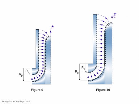
Call ( Rα ) the inner radius of the negative armature and ( Rβ ) the outer radius of the positive frame. We always have ( Rβ = Rα + e ).
The capacity of each quarter of cylindrical capacitor is equal to: